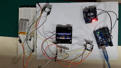
Aruino board with Remote Sensing using X-bee module.
1.Project summary: -
In this project
we gonna interface a temperature sensor and a simple digital switch sensor
which would be read by router X-Bee module and data of both sensor would be
send in API mode to coordinator.
This project can
be made with few simple steps. And picture of our project is shown below.
 |
Figure
1: Remote sensors sensing
with X-bee.
|
2. Components & software required: -
In this project we are using X-bee module in the star connection.
Hardware components: -
· Arduino board.
· Three X-bee modules.
· Two temperature sensor
LM35.
· Male to female jumper
wires.
· Male to male jumper
wires.
· Bread board.
· And two external power
supply for X-bee boards.
Software: download both software in your pc or laotop.
Arduino software (IDE): Arduino software download here
· XCTU software: XCTU sofyware download here
 |
| Figure 2: component require. |
3. Connections: -
In this project
we are want to make a star connection of X-Bee module that can communication
with each other. So a proper connections are really required to make work of our project.
Connection
table: -
3.1. Arduino board with X-Bee
S no.
|
X-bee pins
|
Arduino board
|
1.
|
VCC pin 1 of X-bee
|
3.3v pin
|
2.
|
GND pin 10 of X-bee
|
GND
|
3.
|
TX pin 2 of X-bee
|
D0 or any other pin
which you make for Serial input
|
4.
|
Rx. Pin 3 of X-bee
|
D1 pin.
|
 |
Figure 3: Co-ordinator with Arduino board. |
3.2. X-Bee with temperature sensor: -
S no
|
X-bee
|
Temperature sensor
|
||
1.
|
Pin 1
|
3.3v supply
|
Supply voltage
|
3.3 or 5v
|
2.
|
Pin 10
|
ground
|
Ground supply
|
ground
|
3
|
Pin 14 (vref)
|
3.3v
|
Output pin
|
Pin 18 on X-bee
|
4
|
Pin 18 ADC
|
Output pin of temperature sensor
|
||
 |
| Figure 4: Router connections with Temperature sensor LM35. |
Do the
connection for Router_1 and Router_2
same as show in the table two.
4. Making of the project step by steps: To perform this project please follows the following steps
Step 1: - Configuring all three of X-bee.
As we have
learned how to configure the x-bee module in XCTU software in our previous project so
configure the below X-bee module in below configurations.
Co-ordinator: - a coordinator is receiver node of star
connection where ever X-Bee sends its data.
Set the parameter in below format.
Set the parameter in below format.
- Pan id: 1111.
- Scan channel: 11.
- Baud rate: 9600.
- Parity bit: none.
- Stop bit: one stop bit. And keep all the setting as it is.
 |
Figure 5; co-ordinator configuration. |
Router 1: - this X-bee
takes analog data from temperature sensor and convert the analog data in digital form. And send data in API frame.
- PAN id: 1111.
- Scan channel: 11.
- JV (joint verification): enable.
- Destination address high: 0013A200 (Serial address high of Co-ordinator X-bee).
- Destination Address low: 41241D89 (Serial address low of Co-ordinator X-bee).
- Node identifier: Router 1 (Set your router name).
- Baud rate: 9600
- Parity bit: None.
- Stop bit: one stop bit.
- AD1/DIO1 configuration: Digital input [3].
- AD2/DIO2 configuration: ADC [2].
- IR sampling rate: BB8 in HEX (3 sec or 3000 milli sec).
 |
Figure 6: Router_1 configurations. |
Router_2: - Do
the same configuration for third X-bee as Router_1 and name that one as
Router_2. And just change the Sampling rate different so that information do
not get collide at
coordinator.
coordinator.
 |
Figure 7: Router_2 configuration. |
I made the
sampling for Router_2 is 1388 (5000 milli second.). Now when all of three X-bees
have been configured thus we can start to play now.
Step_2: - Make all the connection and set the
hardware as shown in the diagrams.
 |
Figure 8: connections of all X-bee. |
Make all the
connection in the project as shown in the connection table and please be
conscious, do not connect x-bee with high supply voltage, otherwise it may
harm or module.
Step_3: Now burn
the Arduino with our code and open up the serial monitor to see the Value of Temperature and Digital switch on the serial monitor.
 |
Figure
9: Remote sensor sensing with X-bee, Arduino code.
|
5. Result: -
In our project two sensors are connected to the each of router X-bees, one is temperature sensor and other one is Digital switch. Those are being sampled at
different sampling rate on each router X-bee module. And all the X-bee modules
are connected in the star connection and routers are communicating with coordinator
X-bee.
The result of
this project can be seen on serial monitor of Arduino software.
 |
Figure 10: Result on the Serial monitor. |
6. Project
specifications: -In this project we are configuring
x-bee module for transmitting a digital sensor data and a analog sensor data and
reading this data on serial monitor of Arduino software (IDE).
· This project can be
used on industrial and domestic level both. And can be place where we want to
monitor and data like temperature, humidity, moisture any kind of analog pr
digital sensor.
· Range of x-bee in this
project is around 30 meter and if we professionals X-bee module and range could
1000 to 2000 meter also, which can be used to monitor sensor and communicating
in many industries.
7. Arduino codes for this project: - Down load and upload this below code in you coordinator side Arduino board.
Arduino board code for remote sensor monitoring using X-bee.
Please share and subscribe my blog for more Arduino projects.
Comments
Post a Comment