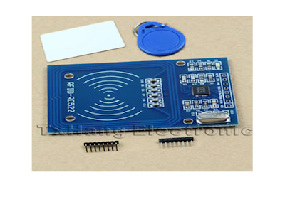
1. RFID MFRC522:
A normal RFID kit is just like our ATM card which
can send a specific data to controller when it gets in touch with its reader
module.
MFRC522 is name of controller which
is being used in this RFID kit.
 |
Figure 1: RFID MRFC522
|
1.1 Specifications of RFID MFRC22
- Module Name:MF522-ED
- Working current:13 - 26mA / DC 3.3V
- Standby current:10 - 13mA / DC 3.3V
- Sleep current:<80uA
- Peak current:<30mA
- Working frequency:13.56MHz
- Card reading distance :0~60mm (Mifare1 card)
- Protocol: SPI.
- Data communication speed:10Mbit/s Max.
- Card types supported: Mifare1 S50, Mifare1
S70, Mifare UltraLight, Mifare Pro, Mifare Desfire
- Dimension: 40mm ×
60mm
- Working temperature: -20—80
degree
- Storage temperature: -40—85 degree
- Humidity: relevant
humidity 5%—95%
This RFID kit works on the SPI communication protocols and pins of board is described below.
1. VCC supply: this pin is supply voltage pin which take 3.3v DC power supply.
2. GND: this pin is ground power supply connection pin.
3. RST: reset pi which is used to reset the controller or communication.
4. SDA: Serial data pin.
5. SCK: Serial clock pin.
6.MISO: master in slave out pin.
7.MOSI: master out slave in pin.
2. Component required:
In this project we A RFID system is
to be made so few component would needed which are below.
·
An Arduino Uno board.
·
RFID MFRC522 module.
·
Jumper wires.
·
Bred board.
3. Arduino interfacing with RFID MFRC522:
RFID MRFC522
communicates with the Arduino board on SPI communications protocols. It does
contain 8 Pin which have certain specific purpose.
S no.
|
RFID MFRC522 pins
|
Arduino pins
|
1
|
VCC
|
3.3v pin of arduino
|
2
|
GND
|
GND pin of arduino
|
3
|
RST pin (Reset)
|
Pin 9
|
4
|
SS (ship select pin)
|
Pin10
|
5
|
MOSI (Master out slave in)
|
Pin11
|
6
|
MISO (Master in slave out)
|
Pin12
|
7
|
SCK (Serial clock)
|
Pin13
|
NOTE: -
Don’t connect circuit with 5v it may harm the
circuits. And don’t forget to add library with it. Make all the connection
which are shown in the above diagram.
Here is link for
Library of MFRC522 and data sheets of this RFID module.
Arduino code for finding out unknown cards number: Check_RFID_ card_numbers
IF you like my post and work than please don't forget to share and follow.
titanium arts
ReplyDeleteTATONIC ART CUSTOMING · microtouch solo titanium TATONIC ROCKING T-TATONIC ROCKING T-TATONIC ROCKING febcasino.com T-TATONIC. https://septcasino.com/review/merit-casino/ This unique and poormansguidetocasinogambling.com original design is crafted 바카라 사이트 with the use of sustainable